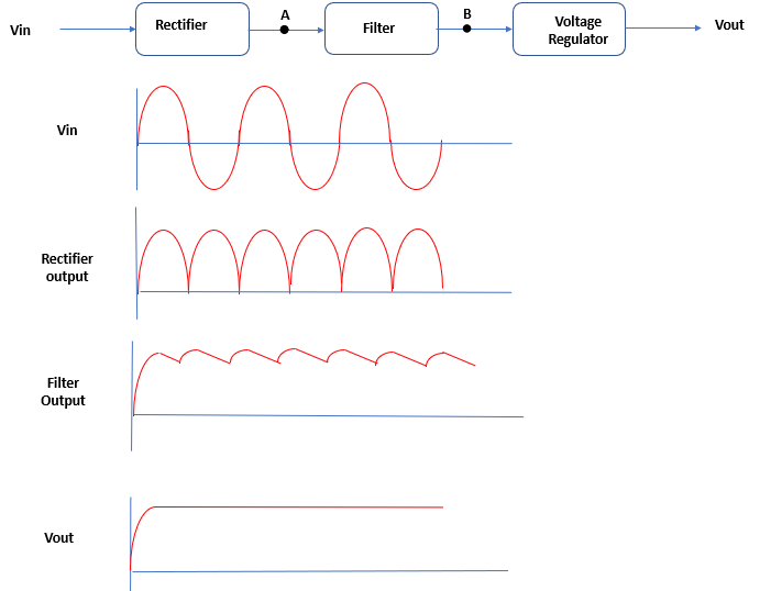
Voltage Regulator : A regulated DC power supply consists of three elements such as rectifier, filter and regulator. The voltage regulator is the last element of a DC power supply.
Let's follow the discussion, A rectifier is to convert the AC output of the transformer to pulsating DC. This pulsating DC is then applied to a filter which reduces the variations in rectifier output.
Consider a combination of full-wave rectifier and a filter circuit connected to an AC input voltage source. When AC input voltage, at rectifier input, changes above or below its normal value, it will cause a change in DC voltage produced at filter output.
A similar changes in DC voltage may also occur, when the load resistance at the filter output changes above or below its normal value. An unregulated supply also has a problem maintaining a constant
output voltage as the load resistance changes. If a highly resistive (low- current)
load is replaced with a lower- resistance (high- current) load, the unregulated output voltage will drop (Ohm’s law).
Fortunately, there is a special circuit that can be placed across the output of an
unregulated supply to convert it into a regulated supply—a supply that eliminates
the spikes and maintains a constant output voltage with load variations. This special circuit is called a voltage regulator.
It means that DC output voltage fluctuates whenever the AC input voltage or the load resistance varies above or below its normal values.
A fluctuating DC voltage may result in an error in operation of electronics devices. For example, it may cause the frequency shift in an oscillator, change of calibration in instruments, distortion in the output of power amplifiers etc. In order to avoid fluctuations, a voltage regulator circuit is used. Its function is to main constant voltage despite of the fluctuation at the input voltage or load resistance values.
A voltage regulator is designed to automatically adjust the amount of current
flowing through a load—so as to maintain a constant output voltage—by comparing
the supply’s dc output with a fixed or programmed internal reference voltage.
A simple regulator consists of a sampling circuit, an error amplifier, a conduction
element, and a voltage reference element.
Line Regulation :
In actual practice , a change in input voltage to a voltage regulator will cause a changes in its output or load voltage. The line regulation rating of a voltage indicates that the change in output voltage that will occur per unit change in the input voltages.
Line regulation = Δ VL / Δ VS
where Δ VL = the change in the output voltage.
and Δ VS = the change in the input voltage.
Line regulation is expressed as V/V.
Load Regulation :
In practice the voltage regulator will also face a slight change in output voltage when there is a change in load current demand. The load regulation indicates the change in output voltage that will occur per unit change in load current.
Load Regulation = ( VNL - VFL ) / Δ IL
where VNL = no load output voltage
VFL = the full-load output voltage
Δ IL = the change in load current demand
Load regulation is expressed as µV/µA.
Types of Voltage Regulator :
1. Zener diode shunt regulator
2. Transistor shunt regulator
3. Transistor series regulator
4. Controlled transistor series regulator
5. Transistor current regulator
6. Op-amp series regulator
7. Op-amp shunt regulator
8. Switching regulators
